BD sensor can work with other probe sensor like proximity,tap,switch.
It means the bdsensor only for scan or real_time_level, tap/proximity sensor for homing and QGL/z_tilt.
Be careful when using it at the first time, for example, you can use an old PEI plate for testing.
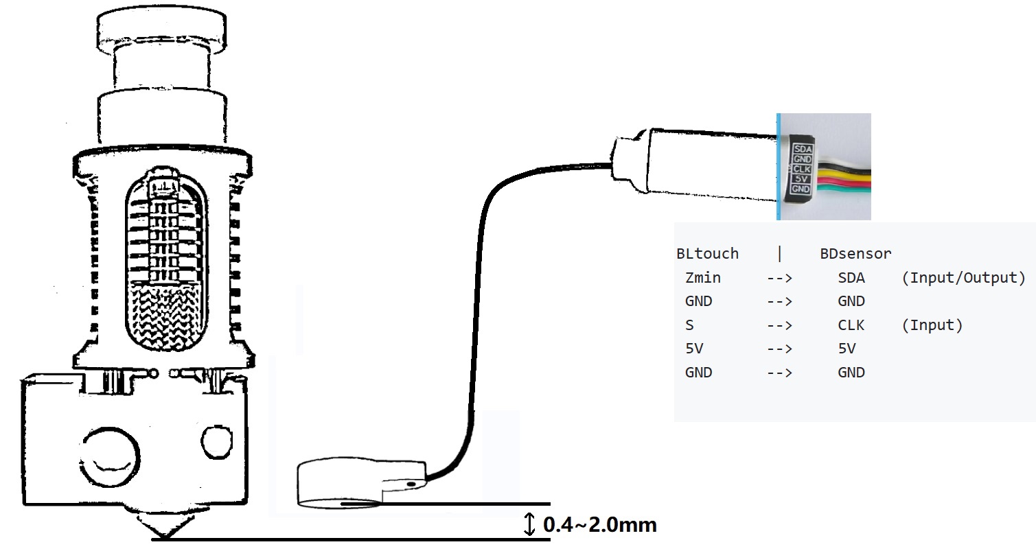
the wires CKL and SDA of BDsensor can be connected to any GPIO pins of your board. You can also connect the BDsensor cable into the Bltouch port directly (except all the boards from MKS), for example:
BLtouch    |    BDsensor
 GND      -->     GND
 5V       -->     5V
 S        -->     CLK/SCL    (Input)
 GND      -->     GND
 Zmin     -->     SDA    (Input/Output)
Since some of the pins in the connectors on the mainboard maybe not connected to the gpios of MCU directly (e.g. there maybe a filter capacitor on them or isolated by mosfet, diode or optocoupler, but it’s OK if they are isolated by resistors or pullup/pulldown by resistors), they cannot work with BDsensor. and the firmware will report connection error. For example
https://raw.githubusercontent.com/markniu/Bed_Distance_sensor/new/doc/images/Connection1.jpg
Note: The black cable is original designed for the IPEX wireless antenna, it is a little stiff, please don’t bend it too much.
ssh into your Klipper printer and execute the following commands:
2.1 Download
cd  ~
git clone https://github.com/markniu/Bed_Distance_sensor.git
2.2 Install the software
~/Bed_Distance_sensor/klipper/install_BDsensor.sh
cd ~/klipper/
sed -i '/BD_sensor/d' src/Makefile;echo "src-y += BD_sensor.c" >> src/Makefile
make menuconfig
2.3 Compile firmware
make
Make sure there is Compiling out/src/BD_sensor.o on the SSH while make.
If you don’t want to see the “dirty” on the mainsail, you can run ./make_with_bdsensor.sh instead of make
2.3 Flash firmware
Flash firmware into the MCU or the CANbus toolhead board which the BDsensor connected.
make flash
Different boards have different configuration in the steps make menuconfig and make flash, please read the document of the board from the factory, we didn’t change any of that.
Paste the following [BDsensor] section into your printer.cfg
Modify the sda_pin and scl_pin to yours, also do not forgot to disable other probe section like [bltouch] or [probe].
Make sure there is endstop_pin: !PB2 in the [BDsensor], and please modify the PB2 to the actual pin that the tap sensor connected.
[BDsensor]
# Don't use aliases for the board pins
sda_pin: PB1 # example of connecting to main board Creality V4.2.7
scl_pin: PB0
#scl_pin:MKS_THR:gpio20 # example of connecting to CAN module like MKS THR42
#sda_pin:MKS_THR:gpio11
#scl_pin:host:gpio17 # example of connecting to GPIO on RaspberryPi
#sda_pin:host:gpio27
delay: 10 # you can set it 10 if the BDsensor version is >=1.2
z_offset:0 #  within -0.6 to 0.6mm
x_offset: -34
y_offset: 0
no_stop_probe: # fast probe that the toolhead will not stop at the probe point,disable it by commenting out.
position_endstop: 1.2 #the triggered position, recommend value is 1~2.8
collision_homing:0 #  set it 1 to enable homing with nozzle collision sensing.
collision_calibrate:0 # set it 1 to enable auto calibrate BDsensor with nozzle collision sensing.
#QGL_Tilt_Probe:0 # set 1 to enable probe up and down when do quad_gantry_level,default is 1
speed:3 # this speed only works for the z tilt and PROBE_ACCURACY command.
homing_cmd: G28 # needed by the auto calibration.the default is G28, please set it G990028 if there has [gcode_macro G28]
endstop_pin: !PB2 #connect to the tap/proximity sensor
Enable zero_reference_position
[bed_mesh]
horizontal_move_z:1 # 0.7~1.0mm is recommended
zero_reference_position: 150, 160 # Set this value to be the same as home_xy_position that is in the section safe_z_home
....
M102 S-1     # gcode command to read sensor information
M102 S-2     # gcode command to get one distance value in millimeter
M102 S-7     # put a metal close to the sensor about 1mm,and send this command to get one distance value in raw (0~1015),
Please check the connection by M102 S-1. Here is an example of the returned message:
Send: M102 S-1
Recv: V1.0 pandapi3d.com
please check the connection and wire order if it returns blank, make sure there is no signal filter capacitor or diode on the GPIO.
Test it with M119, make sure the tap is worked as expect before homing with G28
Clean the nozzle and level the bed with QGL/z_tilt before calibration
Manual move the Z axis down in the menu until the nozzle just touches the bed plate or G1 Z0
Send calibration command M102 S-6.
After that you can check whether the BDsensor has been calibrated successful by M102 S-5 that will return the raw calibration data which stored in the BDsensor. If the first raw calibration data returned by the M102 S-5 is greater than 400, that means the sensor is mounted too high and needs to be remounted closer to the bed, the recommend value of first data is around 100. also make sure that the value of second data is greater than the first data by more than 10, else adjust the height of z and do calibarte again.
G28
G1 Z1
waiting the toolhead stops then
M102 S-2
Happy printing!