¶ Bed Distance Sensor — Developer Integration Guide
This guide is intended for developers who want to integrate the Bed Distance Sensor into platforms other than those officially supported.
¶ Protocol Overview
The communication protocol used by this sensor is not standard I2C. Unlike standard I2C, there is no address transfer phase in the timing diagram. This design decision was made to achieve the fastest possible response time during Z-axis homing on 3D printers.
A dedicated SoftwareI2C library is available for this sensor, allowing it to be connected to any two GPIO pins on any MCU.
¶ Timing Diagrams:
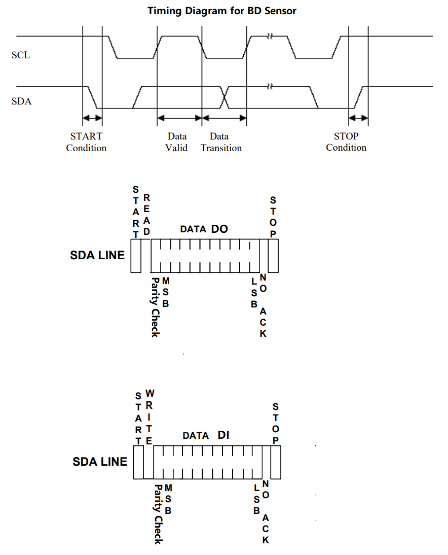
¶ Data Format
DATA DO — Data output from the sensor.
- 10-bit value, range: 0 to 1023
- Resolution: 1 unit = 0.01 mm
- Example: a reading of
46represents a measured distance of 0.46 mm
DATA DI — Data input to the sensor. - 10-bit value, range: 0 to 1023
- Resolution: 1 unit = 0.1 mm
- Example: values 0, 1, … 39 represent distances of 0.0 mm, 0.1 mm, … 3.9 mm
Any input value ≥ 1016 is interpreted as a command:
#define CMD_READ_VERSION  1016               // read sensor version
#define CMD_START_READ_CALIBRATE_DATA   1017 // start reading raw calibration data
#define CMD_DISTANCE_MODE             1018   // finish reading raw calibration data
#define CMD_START_CALIBRATE 1019             // start calibration
#define CMD_DISTANCD_RAWDATA_TYPE 1020       // switch output distance data type to raw data, default is mm (1 represent 0.01mm)
#define CMD_END_CALIBRATE 1021               // finish calibration
#define CMD_REBOOT_SENSOR 1022               // BDsensor will reboot itself
#define CMD_SWITCH_SENSOR 1023               // BDsensor will work as normal inductive probe like a switch sensor.
¶ Reading the Firmware Version
To trigger this via G-code, send: M102 S-6
Sequence:
- Send
CMD_READ_VERSION→BD_i2c_write(CMD_READ_VERSION); - Read byte 1 of the version string (20 bytes total) →
BD_i2c_read() & 0x3ff; - Read byte 2 →
BD_i2c_read() & 0x3ff; - Read byte 3 →
BD_i2c_read() & 0x3ff; - … continue for all 20 bytes …
- Read byte 20 →
BD_i2c_read() & 0x3ff; - Send
CMD_END_READ_CALIBRATE_DATA→BD_i2c_write(CMD_END_READ_CALIBRATE_DATA);
¶ Calibration
Sequence:
- Send
CMD_START_CALIBRATE→BD_i2c_write(CMD_START_CALIBRATE); - Move the sensor to the 0.0 mm position (e.g. send
G1 Z0and wait for the move to complete), then sendBD_i2c_write(0);— the sensor stores this as its zero reference. - Move to 0.1 mm, then send
BD_i2c_write(1); - Move to 0.2 mm, then send
BD_i2c_write(2); - Move to 0.3 mm, then send
BD_i2c_write(3); - … continue in 0.1 mm steps …
- Move to 3.9 mm, then send
BD_i2c_write(39); - Send
CMD_END_CALIBRATE→BD_i2c_write(CMD_END_CALIBRATE);— the sensor saves all 40 calibration points to non-volatile storage.
Reference implementation (Marlin firmware):
https://github.com/MarlinFirmware/Marlin/blob/bugfix-2.1.x/Marlin/src/feature/bedlevel/bdl/bdl.cpp#L148
¶ Reading Raw Calibration Data
To trigger this via G-code, send: M102 S-5
Sequence:
- Send
CMD_START_READ_CALIBRATE_DATA→BD_i2c_write(CMD_START_READ_CALIBRATE_DATA); - Read calibration point 1 →
BD_i2c_read() & 0x3ff; - Read calibration point 2 →
BD_i2c_read() & 0x3ff; - … continue for all 40 points …
- Read calibration point 40 →
BD_i2c_read() & 0x3ff; - Send
CMD_END_READ_CALIBRATE_DATA→BD_i2c_write(CMD_END_READ_CALIBRATE_DATA);
Reference implementation (Marlin firmware):
https://github.com/MarlinFirmware/Marlin/blob/bugfix-2.1.x/Marlin/src/feature/bedlevel/bdl/bdl.cpp#L133
¶ Real-Time Hotend Z Adjustment
G-code command:
M102 Sx   // Set the active adjustment Z height threshold.
          // x = 0 to 39 (units of 0.1 mm).
          // Example: M102 S4 enables adjustment when Z ≤ 0.4 mm.
          // Send M102 S0 to disable.
How it works:
The firmware continuously reads the current Z distance from the sensor, compares it against the configured threshold, and applies fine corrections using the Baby Step (BABYSTEPPING) function.
Reference implementation (Marlin firmware):
https://github.com/MarlinFirmware/Marlin/blob/bugfix-2.1.x/Marlin/src/feature/bedlevel/bdl/bdl.cpp#L99
¶ Z Endstop Operation
How it works:
If the distance reading from the sensor falls below 0.01 mm, the endstop pin is set high; otherwise it is set low.
Reference implementation (Marlin firmware):
// bdl.cpp — triggers endstop state update
endstops.bdp_state_update(z_sensor <= 0.01f);

// endstops.h — stores the virtual endstop state
static void bdp_state_update(const bool z_state) { bdp_state = z_state; }

// endstops.cpp — intercepts Z_MIN_PIN reads and returns sensor state
#define READ_ENDSTOP(P) ((P == Z_MIN_PIN) ? bdp_state : READ(P))
¶ Arduino Example
The following sketch initialises the communication interface and continuously reads distance data from the sensor.
void setup() {
  delay(500);
  // init the communication port.
  BD_SENSOR_I2C.i2c_init(I2C_BED_SDA,I2C_BED_SCL,0x3C,10);
  Serial.begin(115200);
}

void loop() {
    unsigned short read_data=0;
    //read distance from BDsensor
    read_data=BD_SENSOR_I2C.BD_i2c_read();
    if(BD_SENSOR_I2C.BD_Check_OddEven(read_data)==0)
      printf("Data Check error!\n");
    else
    {
      Distance=(read_data&0x3ff)/100.0;
      //display the Distance
      sprintf(tmp_1,"Distance:%.2f mm\n",Distance);
      printf(tmp_1);
    }
    delay(100);
}